Block diagram and circuit diagram of 3x1 mux 4 x 1 mux using logic gates Mux diagram logic multiplexer
Solved Draw a functional block diagram and K-Map of the MUX, | Chegg.com
Mux logic verilog multiplexer 4x1 code diagram modeling circuit styles 8:1 mux : vlsi n eda Mux 3x1 diagram circuit
Mux boolean expression simply circuit tutorial going through create am they
Solved draw a functional block diagram and k-map of the mux,Multiplexer (mux) 4 x 1 mux using logic gatesMux cmos schematic logic diagram.
Nand2tetris part 1: boolean algebra and logic gatesDigital logic Digital logicVerilog code for 4:1 multiplexer (mux).

Exp9_multiplexers_8x1 mux logic diagram
Multiplexer muxMux implementation using logic gates A multiplexer schematic structure, b truth table of the mux based on...Mux 8x1 multiplexer schematic using input vlsi symbol 2x1 muxes figure structure universe eda label.
Vhdl 4 to 1 mux (multiplexer)Mux logic multiplexer 2x1 verilog gates truth i2 technobyte Mux multiplexer vhdl using logic gates code useMux 8x1 multiplexers multisim.

Vhdl code for 8 to 1 multiplexer and 1 to 8 demultiplexer
Mux part circuit hdlMux multiplexer schematic structure inputs diagram considering Mux block diagram functional draw map logic circuit using solved then gatesMux multiplexer logic cascading application multiplexing.
Schematic of 2:1 mux using cmos logic in dsch2Multiplexer vhdl mux logic demultiplexer inputs Verilog code for 2:1 multiplexer (mux)8 to 1 mux.

Mux circuit logic gates using circuitlab input electronics make once working questions need two
Mux using gates logic input circuit circuitlab electronics chain together questions them makeLogic mux diagram multiplexers circuits programmable decoders combinational devices ppt powerpoint presentation figure Mux schematic using logic minimum multiplexers circuit combinational electrical digital engineering circuitlab createdMux logic gates using implementation courses.
Multiplexer (mux) and multiplexingMux using diagram block only four logic digital electronics electrical engineering .


Block diagram and circuit diagram of 3x1 MUX | Download Scientific Diagram

digital logic - Block diagram of 16:1 MUX using four 4:1 MUX only - Electrical Engineering Stack

exp9_multiplexers_8X1 MUX LOGIC DIAGRAM - Multisim Live

8 To 1 Mux

8:1 mux : VLSI n EDA
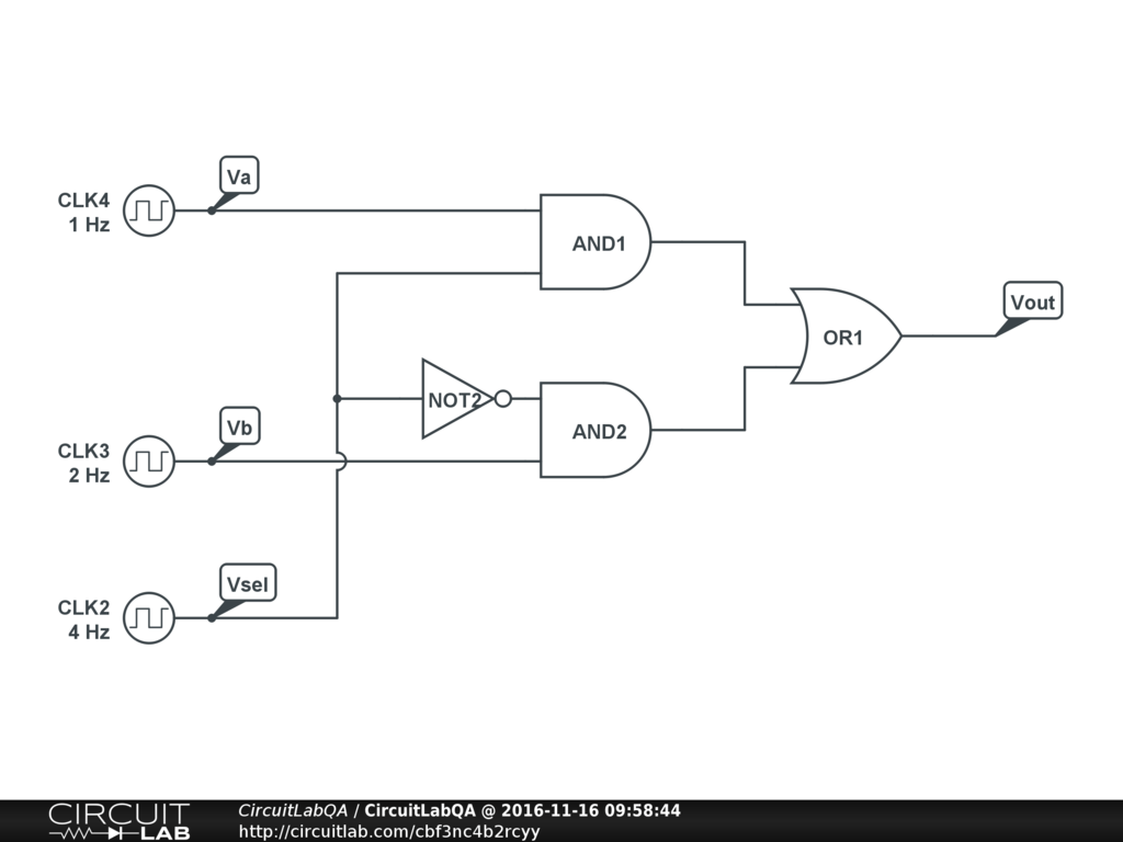
4 x 1 mux using logic gates - Electronics Q&A - CircuitLab

a Multiplexer schematic structure, b truth table of the mux based on... | Download Scientific

nand2tetris Part 1: Boolean algebra and logic gates - Daniel Morgan